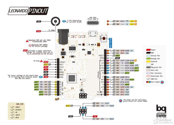
Understanding the Arduino Leonardo ETH Schematic: A Detailed Guide
Are you intrigued by the Arduino Leonardo ETH and its intricate schematic? If so, you’ve come to the right place. This guide will delve into the details of the Arduino Leonardo ETH schematic, providing you with a comprehensive understanding of its components and functionalities. Whether you’re a hobbyist or a professional, this article will help you navigate the complexities of this popular microcontroller.
Overview of the Arduino Leonardo ETH
The Arduino Leonardo ETH is a microcontroller board based on the ATmega32U4. It’s designed to be compatible with the Arduino Leonardo, but with the added feature of an Ethernet port. This makes it an excellent choice for projects that require both wireless communication and a physical connection to a network.
Physical Layout of the Arduino Leonardo ETH
The Arduino Leonardo ETH has a compact and user-friendly layout. Here’s a breakdown of its key components:
| Component | Description |
|---|---|
| ATmega32U4 | The main microcontroller that powers the board. |
| Ethernet Module | Enables the board to connect to a local network via Ethernet. |
| USB Connector | Used for programming and communication with the computer. |
| Power Jack | Accepts an external power supply to power the board. |
| Reset Button | Resets the board to its initial state. |
| ICSP Header | Used for programming the ATmega32U4 via an In-Circuit Serial Programmer (ICSP). |
Understanding the Schematic
The Arduino Leonardo ETH schematic is a detailed representation of the board’s internal connections. To understand it, let’s break down some of its key components:
ATmega32U4
The ATmega32U4 is the heart of the Arduino Leonardo ETH. It’s an 8-bit microcontroller with 32KB of flash memory, 2KB of SRAM, and 1KB of EEPROM. The microcontroller communicates with the other components on the board via a variety of pins, including digital, analog, and PWM pins.
Ethernet Module
The Ethernet module is responsible for connecting the Arduino Leonardo ETH to a local network. It uses the W5100 chip, which is an Ethernet controller that supports TCP/IP, UDP, and other networking protocols. The module is connected to the ATmega32U4 via SPI and provides a 10/100 Mbps Ethernet connection.

USB Connector
The USB connector is used for programming the ATmega32U4 and for communication between the board and a computer. When connected to a computer, the board appears as a virtual COM port, allowing you to upload sketches and receive data from the board.
Power Jack
The power jack is used to supply external power to the board. It accepts a voltage range of 7-12V, which is then regulated to 5V by the on-board voltage regulator. This regulated 5V is used to power the ATmega32U4 and other components on the board.
Reset Button
The reset button is used to reset the board to its initial state. When pressed, it momentarily connects the reset pin of the ATmega32U4 to ground, causing the microcontroller to reset.
ICSP Header
The ICSP header is used for programming the ATmega32U4 via an In-Circuit Serial Programmer (ICSP). This allows you to reprogram the microcontroller without removing it from the board.
Conclusion
Understanding the Arduino Leonardo ETH schematic is essential for anyone looking to develop projects that require both wireless communication and a physical connection to a network. By familiarizing yourself with the board’s components and their connections, you’ll be well-equipped to tackle a wide range of projects. Whether you’re a beginner or an experienced hobbyist, this guide should provide you with the knowledge you need to get started.


